This tutorial shows how to turn an imported VRML static model, made by any 3d modeller, into a dynamic multi-part animated model.
This tutorial is written to accompany the robot demo bring static model to life
This demo requires first that the contents of the files_for_demos.zip file be manually unzipped and put in the folder:
My Documents\Seamless3d\Application Data For Seamless3d\For Robot Demos Only
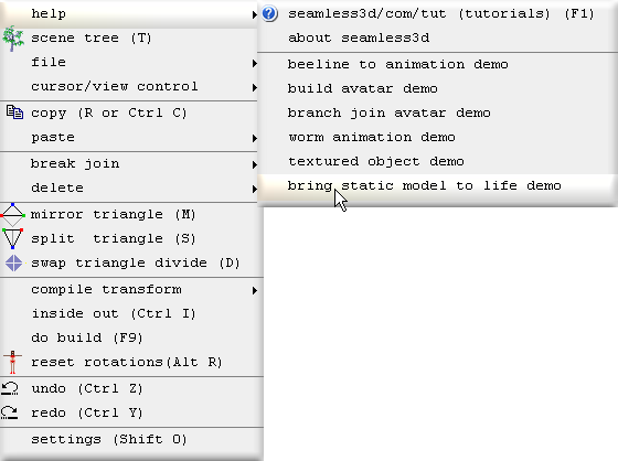
To see this demo, move the mouse to the top left corner of the 3d window and select:
The demo shows all the actions needed to make the static model ready to be animated.
The same Interpolator nodes, ROUTEs and or scripts used for animating standard type vrml models that are made from multiple Transform and Shape nodes, can also be used to animate this model when it is ready to be animated.
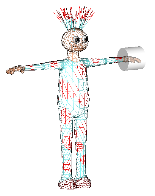
The example static model used here is a model made by Seamless3d that has been converted to a file containing only a single VRML Shape node which contains all the geometry and texture mapping but nothing else (no scripts). If the static model is opened in a VRML browser, the geometry will not be collapsed.
Though the static model could have been made by any 3d modeller, note that the model made by Seamless3d has been made specially suited for single skin mesh animation, extra vertices have been created for the shoulders, elbows, knees etc. to improve the quality of the joints when they bend.
A big advantage of using build nodes is there is no problem in accidently messing up the model because the source static model can be re-imported at any time. Build nodes offer more freedom with what can be done with our work. Once the build nodes have been set up they can be re-used to import any static model that has the same basic shape.
The Basic Idea
Begin
Start the robot demo:
bring static model to life
All of the titles for the robot demo operations will be shown here in bold beginning with the operation number followed by the title itself. Any comments for the operation will be explained under the title.
0. Create A New Seamless File
Click on the new smls file button1. Import Empty Skeleton of Parts
Begin with a pre-made skeleton of empty parts. Part names that begin with l_ are the left parts and names that begin with r_ are the right parts. To avoid using double names for a part, the part for the upper arm for example is referred to by it's joint (shoulder) that attaches it to it's ancestor part.
| Part | Includes |
| shoulder | upper arm |
| elbow | forearm |
| wrist | hand |
| hip | thigh |
| knee | shin & calf |
| ankle | foot |
2. Replace ColorEffect with TextureEffect
Because the static model uses textures we must first replace the ColorEffect node with a TextureEffect node. If this is not done before importing the model into a part node, all of the texture mapping will be lost. This operation should not be done if the model being imported does not use textures such as when the Shape uses "color per vertex" or when the Shape uses only the Material node to colour the geometry.
3. Import Static Model Into a Part
An immediate blue part named model_source is created to contain all the triangles imported from the file, static_model.wrlThis part will be the 1st source of the vertices for the model and will not be modified by any build nodes so it will always contain the original number of vertices.
A "build cycle" is the term used for when ever the build nodes run. (much the same as executing a macro). A build cycle happens automatically each time we modify a field belonging to a build node. In a build cycle each build node runs it's "doBuild" function in sequential order from top to bottom. Collapsing nodes in the scene tree has no affect over a build cycle.
The static model has it's arms straight out horizontally which makes it easiest to select the vertices around the shoulder for the arm parts but if the model is to be used strictly for the H-Anim standard, the arms in the static model must rest downwards.
4. Copy All of the Triangles to the Pelvis
Because TransferBCyl nodes will be used to transfer the ownership of vertices from a part that contains the source vertices to the rest of the parts and because this will result in the source part being modified (loosing ownership of vertices results in loosing vertices), instead of transferring the vertices directly from the 1st source, all of the vertices will first be copied to another part (the pelvis) to be used as the direct source for the TransferBCycle nodes. This is done using a CopyPart node. Note that the demo robot drags the Part nodes from the skeleton to the CopyPart node while holding down the Alt key so that the Parts are dragged as references. Also note that the source node is dropped to the upper half (and to the right) of the CopyPart's icon so that it is dropped as a source node and that the destination part is dragged to the lower half of the icon so that it is dragged as the destination part. The source part is differentiated from the destination part in the scene tree by the blue dot to the left of the referenced part's icon: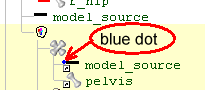
The part model_source is hidden from here on so that the only triangles that will be visible, will be contained in the parts used for the actual model.
5. Place the Avatar to the Floor
The demo robot clicks the bluxxen_height button (-1.75 meters) and positions the feet to this height but had the demo been originaly written for today the zero_height button would be clicked which is compatible for seamless chat and most ofther 3D platforms.6. Move the pivot points
So that the pivot points can bee seen, xRay
 mode is toggled on and xRay edit
 is toggled on to
show the selected part. Note that a part must be selected in order to switch
into xRay mode. The pivot points can be moved using the Part's pivotPoint
buttons and can also be moved by draging them.
is toggled on to
show the selected part. Note that a part must be selected in order to switch
into xRay mode. The pivot points can be moved using the Part's pivotPoint
buttons and can also be moved by draging them.
Because the Part mirror fields are ticked and the leg and arm parts are all prefixed with l_ for the left side and r_ for the right side, the right side will simulataneously be modified when changing the left side.
7. Transfer from pelvis to l_shoulder
To center view on the slected pivot point click and zoom in using the mouse wheel.
Here the first TransferBCyl node is added. TransferBCyl nodes are set the task of selecting vertices from the source part node (the upper reference part with the blue dot) and transferring them to the dest(ination) part (the lower reference part without the blue dot). Transfer refers to ownership. To see who owns what, click
 to toggle color ownership
mode on. For more info on color ownership mode see Colour Coded Ownership.
to toggle color ownership
mode on. For more info on color ownership mode see Colour Coded Ownership.
The vertices from the source (pelvis) are selected using a semi transparent cylinder. The cylinder's proportions are specified by the TransferBCyl's radius and height fields. The cylinder is positioned using the location and orientation fields. The cylinder is visible in the 3d window when TransferBCyl node is selected and while the in field is checked.
The in field is unticked after each TransferBCyl node is added only to speed up the build cycles because with in unchecked the transfer does not have do the time consuming task of measuring which vertices fit within the cylinder thanks to the vertex field remembering which vertices to transfer.
8. Create groups for l_shoulder's vertices
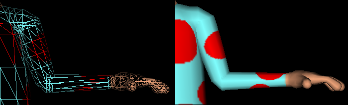
When a part like the shoulder bends during animation, we can improve the quality of the joint by making it so that different groups of vertices at the joint rotate fractions of the full amount of the rotation field for the part.Here we see how the shoulder and elbow would look if all the vertices for these parts are allowed to all bend the full amount of the part's rotation field:
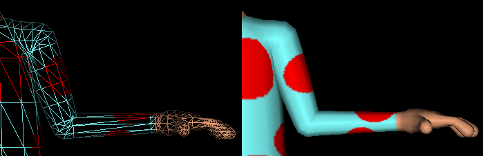
and here we see groups of vertices in the shoulder and elbow bending varying amounts:
To transfer the vertices into these groups for the arm, the groupingHeight field is used. The groupingHeight field specifies a portion of the cylinder that is a slice of the cylinder's base:
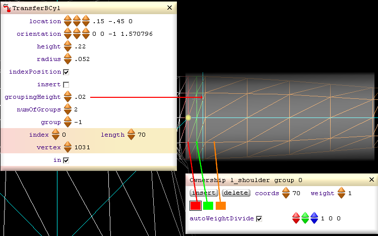
A Part node will always have at least one group of vertices (even if the group contains no vertices). The TransferBCyl's numOfGroups field specifies how many extra groups will be set for the destination part.
The red group of vertices will rotate only 1/3rd the full amount of the shoulder's rotation field.
The green group of vertices will rotate 2/3rds the full amount of the shoulder's rotation field.
The orange group of vertices will rotate the full amount of the shoulder's rotation field.
When the TransferBCyl's numOfGroups field specifies 1 or more groups, the indexPosition field should be ticked.
9. Transfer from pelvis to l_elbow
10. Transfer from pelvis to l_wrist
11. Transfer Vertices for the Right Arm
12. Transfer from pelvis to l_hip
13. Transfer from pelvis to l_knee
14. Transfer from pelvis to l_ankle
15. Transfer Vertices for the Right Leg
16. Transfer pelvis to tummy0
Because the parts, tummy0, tummy1 thorax, neck0, neck1 and head are parts for the spine and bend much the same as snake joints (each part only needs to bend in small amounts), these parts will not be divided into smaller groups like the parts were for the limbs.17. Transfer pelvis to tummy1
18. Transfer pelvis to thorax
19. Transfer pelvis to neck0
20. Transfer pelvis to neck1
21. Transfer pelvis to head
With the last lot of vertices transferred to the head, the pelvis is left with only the triangles that are intended to stay owned by the pelvis.Demo Completed
Animating The Model
Animating this model will be the same as it is for animating the model in the
nurbs lathe avatar
Making Modifications to the TransferBCyl Fields at a Later Date
One of the great advantages of using build nodes is one can go back in time and make modifications to one's work. However this freedom comes with the possibility of one being able to write bugs that cause a build cycle to malfunction. For example if a TransferBCyl's in field is unchecked and the cylinder is changed to select different vertices and there are other TransferBCyl nodes that come after in the build cycle which have their in fields unchecked, they are likely to no longer be locked into relevant vertices which can result in them indexing vertices that do not exist by the time they get their turn to function. This problem is easily avoided however if before modifying a TransferBCyl node's fields, the user right clicks on the build node and selects:
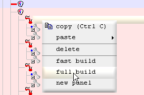
This causes the selected node and all build nodes that come after in the build cycle to have their in field checked if they have one.
A full build cycle will make things slower (only for editing) but the in fields can be all unchecked back just as easily by right clicking on the same build node and selecting fast build. If your computer is fast or if you prefer to always play it safe, consider permanently leaving the in fields checked so that indexing will always adjust dynamically when ever changes are made, any where in the build cycle. If you take this approach, it is worth un-checking the indexPosition field for parts such as the back bone parts that dont need it.
[3d Modelling Software] [Tutorials] [Forum] [Features] [Download] [Gallery] [FAQ] [Worlds] [Avatars] [Links] [Thyme]