Nurbs Patch Avatar
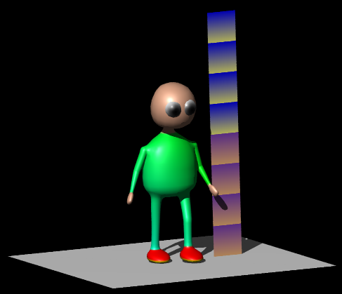
The demo shows all the clicks to make a curvy avatar out of 3 nurbs patches converted from 3 nurbs lathes. NurbsPatches are not only very powerful they are very intuitive. A complete beginner will have fun controlling a nurbs patch by dragging the control points. Although one can begin with this tutorial it will be easier to follow after doing the ultra easy nurbs lathe avatar and/or the worm_animation tutorials.
Begin
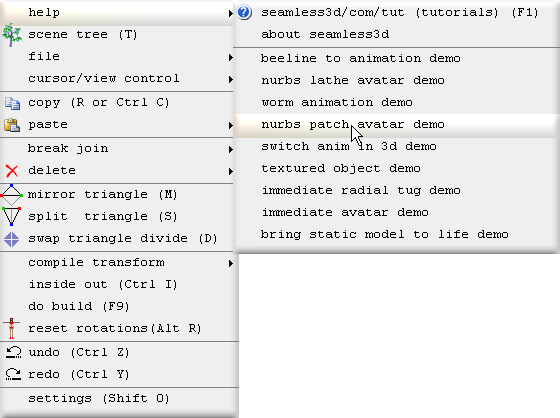
Start the robot demo by moving the mouse to the top left corner of the 3d window and selecting nurbs patch avatar demo:
All of the titles for the robot demo operations will be shown here in bold beginning with the operation number followed by the title itself.
Many believe a tutorial with this much info is beyond their comprehension or is not going to be any fun to follow. However this tutorial does not use any mathematics more complex than one would need to go shopping and we should take time to get familair with new concepts so that only baby steps are taken. If we enjoy modelling and relax enough to be able to enjoy the moment this tutorial should be fun.
Operations 0 to 10 is a complete tutorial that teaches how to make static yet sophisticated curvy models using nurbs patches.
Operations 0 to 22 is a complete tutorial that teaches how to make a skinned animated avatar.
Operations 23 to 24 continue for those who wish to refine their avatar. These operations
show how to fuse the arm and leg nurbs patches to the torso so that the limbs join on more smoothly.
Operations 25 to 41 takes the refining further by editing the torso's poly map so
that the arm's and leg's vertices match up with the torso's vertices to make a perfect
fit.
0. Create a new Seamless file
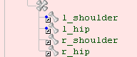
Click on the new smls file button1. Create a skeleton of parts
For our avatar, create a structure of parts and name them as shown:
![]()
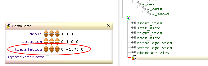
2. Add floor & height guide
Before we start it is important to add a floor and height guide by clicking
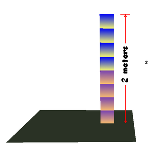
The floor is set to -1.75 meters which is the standard Blaxxun floor level in relation to an avatar. For a different standard that uses a different height for the floor change the height by changing the translation field for the Seamless node we just imported:
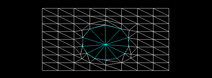
3. Add lathe for torso, neck & head
To help us navigate through the scene tree a pink GroupBuild node is added to contain all of the nodes that generate the geometry.
A single NurbsLathe  is added to sketch out the mesh for the torso, neck & head. Our
NurbsLathe only references the pelvis but this mesh will later be owned by the pelvis,
tummy0, tummy1, thorax, neck0, neck1 & head parts which can be collectively referred
to as the central parts:
is added to sketch out the mesh for the torso, neck & head. Our
NurbsLathe only references the pelvis but this mesh will later be owned by the pelvis,
tummy0, tummy1, thorax, neck0, neck1 & head parts which can be collectively referred
to as the central parts:
4. Add lathe for arm
A single NurbsLathe
is added referencing the l_shoulder to generate all of the geometry for the arms:
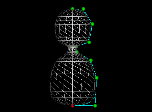
5. Add lathe for leg
A single NurbsLathe is added referencing the l_hip to generate all of the geometry for the legs. The
lathe is first rotated upside down so that the control points are indexed in order
from the hip to the ankle. Seamless3d utilises how rings of vertices are indexed
for a number of different tasks. We should always have the base ring that joins
onto the torso begin at index 0. However if we by mistake do not adhere to this
rule there is a command that will reverse the order of the control points for us
that does not change the shape.
6. Copy left to right
We could create the right limbs the same way we made the left but it is much less work to copy the triangles from the l_shoulder and l_hip to the r_shoulder and r_hip.To do this drag a CopyPart node
 from the new node bar and add it to our pink group:
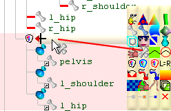
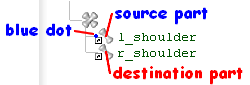
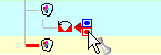
Some build nodes such as CopyParts can reference parts in 2 different ways, as a source and as a destination.
A source part is distinguished from a destination part by its blue dot:
When we drag a part node to a build node as a reference we hold down the Alt key. When we add our part reference as a child node of our build node we drag it to the right of our build node. If our build node has the option of referencing source as well as destination parts 2 small boxes appear to the right of the build node. We must either drag our part to the blue dot which will make it a source reference or drag it to the red dot which will make it a destination reference before letting go of the mouse button to drop the node:

In this operation we add the left parts as source parts and the right parts as the destination parts:
and check the CopyPart's mirrorX field:
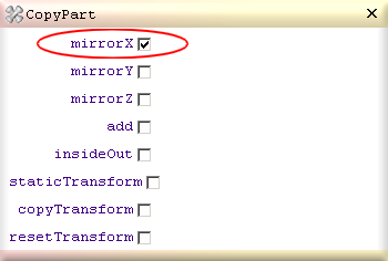
It is important that the CopyPart node is added after the lathe nodes. If it was inserted before the lathe nodes it would be at a stage in the build cycle before there are any triangles to copy.
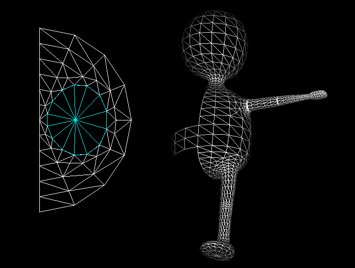
7. Convert lathes to patches
The NurbsLathes are converted to NurbsPatches by right clicking on each of the NurbsLathes and selecting convert to patch: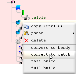
When a lathe
is converted to a patch
 the patch comes with a stem
 node plugged into it and a ColorSweep
 as a sibling of the patch. The ColorSweeps are deleted because they are not
wanted
at this stage.
as a sibling of the patch. The ColorSweeps are deleted because they are not
wanted
at this stage.
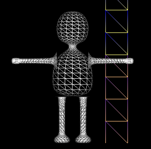
8. Tug torso neck & head points
The NurbsPatch's mirrorTug field is checked so that what ever we drag on one side (left or right) of the patch's control points the other side will mimic in mirror form. Set like this very few tugs are needed to make this elegant shape: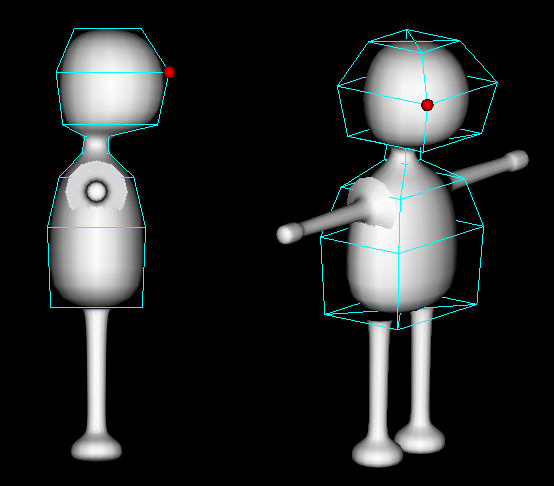
9. Tug arm points
When tugging the arm's or leg's control points the mirrorTug field is not very useful but we can take advantage of the sameViewPositionTug field which also allows us to drag 2 control points at once. When this field is checked and we drag a vertex that looks like it is in the same position of another vertex due to our view orientation, both vertices get dragged along.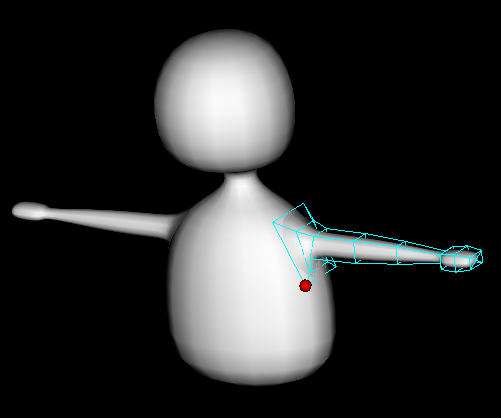
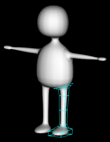
10. Tug leg points
11. Optimize vertex rings for torso
The stem
is the node that generates the triangles for the patch
. If we un check
the stem's
mould field, we can see the triangles as a 2d poly map.
A poly map is much like a texture's UV map. No matter how big or complex the patch's
shape may be, all of the coordinates will fit within a 1 by 1 unit square.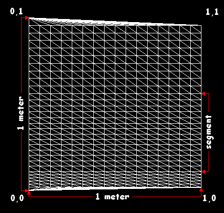
When a lathe is converted to a patch the stem will be set to contain a single segment that will span the full height of the poly map. When the stem's length button is incremented the selected segment is divided into 2 segments. The height of the selected segment can be adjusted by the height field and the number of triangle bands can be adjusted by the bands field.
By default the stem's xJoinEnds field is checked. This causes the east edge vertices to be joined to the west edge vertices. This will result in east and west edge vertices looking dark due to how the normals are generated from the triangle faces but this will not pose a problem after the poly map is moulded into shape by the patch.
A segment is selected by the stem's index button.
12. Optimize vertex rings for arm
Rings are made denser for where the shoulder, elbow and wrist will bend.13. Optimize vertex rings for leg
Rings are made denser for where the hip, knee and ankle will bend.14. Move pivot points
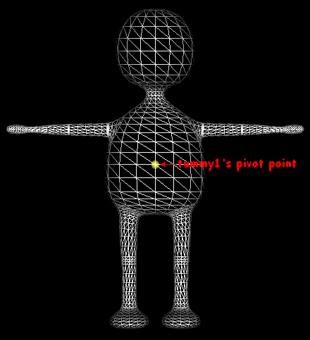
To be able to animate our avatar we must move each part's pivot point (the point at which the part rotates around) to the appropriate location. To move a part's pivot point, select the part and use the buttons from the horizontal tool bar or write in the values directly to the parts's
pivotPoint field.
buttons from the horizontal tool bar or write in the values directly to the parts's
pivotPoint field.Same as with most other non rotation buttons, they increment and decrement in 1 centimeter amounts and 1 millimeter amounts when the control key is held down.
The yellow dot displayed in the 3d window shows the location of the selected part's pivot point:
If you have trouble seeing the pivot point, zoom in using the mouse wheel or use
the zoom
 buttons. To center the view around a pivot point click the
 button.
When moving the pivot points the yellow dot should be viewed from both front on
 and side on

Because pivot points are relative to their parent part, you should move the pivot points beginning from the top part in the scene tree (pelvis) and work your way down to the last part (r_ankle). If you need to move a part's pivot point without changing the location of any of the children pivot points, hold down the Alt key while moving the pivot point.
15. Transfer ownership for torso, neck & head
Unlike the nurbs lathe avatar that uses a separate triangle mesh for each part we will here allocate different portions of the mesh that form the torso, neck and head to the pelvis, tummy0, tummy1, neck0, neck1 and head parts. This will result in triangles between the parts containing vertices owned by more than one part. These triangles will stretch when animated which makes for a more realistic and interesting skin effect for our avatar.To see which part owns a portion of vertices click
 for coloured ownership mode.
Because the NurbsPatch
that generates the mesh for the central parts references the pelvis part,
all of the vertices are owned by the pelvis before any vertices are transferred.To transfer the vertices from the pelvis to the other parts a TransferOwnership
After the part is added as a source reference a blue dot will be shown to the left of the reference to distinguish it from the destination part references.
The destination part references are added the same way except they are dragged to the red dot:
The pelvis is referenced twice both as the source part and a destination part. 6 elements are set for the numOf and qty array fields using the length button. The 6 elements specify how many vertices are owned by the 6 central parts: pelvis, tummy0, tummy1, thorax, neck0 & neck1. We do not need or want an element for the head part because the last destination part referenced by the TransferOwnership gets to own the remaining vertices if no element is specified for it.
The green marker
 in the scene tree shows which destination part corresponds to the
selected element.
in the scene tree shows which destination part corresponds to the
selected element.When in coloured ownership mode the vertices owned by the selected part are coloured white. When a TransferOwnership node is selected the vertices owned by the marked
part are coloured white.The qty (quantity) field is set to 16 for each element because the rings of vertices that make up the mesh contain 16 vertices. The numOf field specifies how many quantities (how many rings).
The beginSP (begin with a single point) check box is checked to treat the first single vertex as a whole quantity (as a whole ring).
16. Transfer ownership for arms
This is much the same as the previous operation but note for the arms the qty field is set for 12 for each ring and the beginSP field is left unchecked.17. Transfer ownership for legs
This is much the same as the previous operation but note for the legs the qty field is set for 14 for each ring. Same as for the arms the beginSP field is left unchecked.18. Set vertex weights
We could animate our avatar now the same way as shown in the nurbs lathe avatar tutorial. However in this operation we will make the arms and leg joints bend smoother by specifying rings in the joints to rotate at a fraction of the part's rotation field:
The amount a ring (or group of vertices) rotates for a part is specified using the Part's weight field. 1 equals a full rotation where as .5 equals half the amount.
The coordGroup field specifies how many vertices are contained in the ring so this matches the number of staves specified by the stem node that built the limb.
We should always work in coloured ownership
mode when setting different groups of weighted vertices because the different
groups will be shown in different colours.
So long as our NurbsPatches's control points are indexed in order so that they ascend from the base of the limb to the end all will work out fine by only specifying how many vertices we want for each group because the stem node generates the order of the vertices consistently.
There is no need to specify a weight of 1 for any of the rings because if a vertex is not specified it will rotate the full amount. For example for the knee the first ring will rotate one third the full rotation (weight set to .333) the next ring 2 thirds (weight set to .666) leaving the rest to rotate the full amount.
Shoulder
|
Hip
|
|||||||||||||||||||||
Elbow
|
Knee
|
|||||||||||||||||||||
Wrist
|
Ankle
|
19. Color torso, arms & legs
20. Color neck, head & hands
21. Color Feet
22. Add eyes
23. Fuse arm to torso
Our arms can look like they join quite well at the right angle especially from a distance but if we get up close and view from the wrong angle we can see how far some of the vertices are from the torso: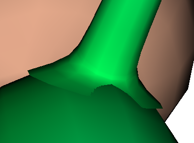
We can easily make an improvement by making the first ring of vertices in the arm lie exactly on the torso's surface:
To do this operation we will use a FuseSurface node. A FuseSurface node has a lot of fields but for this operation we will only use its qty field and its spread button. All we have to do is:
- Plug a FuseSurface node into the torso's stem node.
- Plug the arm's NurbsPatch into the FuseSurface.
- Set the qty field to 12 (the same number of staves the arm is built with)
- Click the spread button.
- Hold down the do build cycle button until the arm's base vertices home in to their final position (which takes about a second)
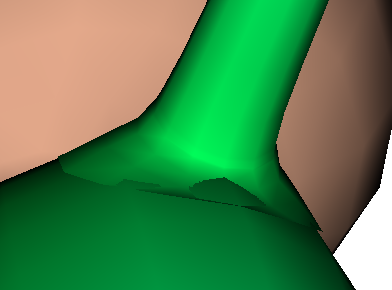
24. Fuse leg to torso
This is much the same as for the arm but note for the leg qty is set to 14.25. Check autoIn
Because operations 25 to 41 are aimed at showing how to hand edited poly maps, now is a good time to check the Seamless node's autoIn field. By setting the
autoIn field we let the Seamless node automatically check and uncheck
the in field for FuseSurface, JoinedVertex
and TransferBCyl nodes. So long as we check the
autoIn field at this stage we do not need to concern ourselves with
the details of what it does. In short, autoIn
protects us from leaving nodes locked into indexing vertices that are no longer relevant and optimizes performance for
tugging nurbs control points.
node's autoIn field. By setting the
autoIn field we let the Seamless node automatically check and uncheck
the in field for FuseSurface, JoinedVertex
and TransferBCyl nodes. So long as we check the
autoIn field at this stage we do not need to concern ourselves with
the details of what it does. In short, autoIn
protects us from leaving nodes locked into indexing vertices that are no longer relevant and optimizes performance for
tugging nurbs control points.26. Isolate triangles for pelvis & thorax
An ExitBuild node stops all nodes functioning after
it.
Because we do not want to be confused by the functionality of any of the build nodes
after the NurbsPatches, an ExitBuildnode is inserted between the pelvis's NurbsPatch
and the eye's SphereBuild:
node stops all nodes functioning after
it.
Because we do not want to be confused by the functionality of any of the build nodes
after the NurbsPatches, an ExitBuildnode is inserted between the pelvis's NurbsPatch
and the eye's SphereBuild: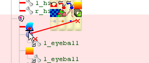
In order to isolate the triangles for the pelvis and thorax so that we can hand edit their polar maps later while leaving the rest of the triangles be computer generated, we will make the central parts be generated by 4 separate stem nodes in this operation. To avoid needing to create all of the segments from scratch, 3 copies of the original stem are made. In subsequent operations unwanted segments in each of the stem nodes will be deleted. 3 of the stems are given different parts to reference and only the pelvis and thorax stems are left with a FuseSurface plugged into them.
27. Set bands for neck & head
Because we do not want to be confused by the triangles generated by any of the other cloned stems, we work with the pelvis, tummy0 and thorax parts hidden. This operation involves no more than deleting the first 2 segments and unchecking the beginSP field.28. Set bands for tummy
The beginSP and endSP fields are unchecked and the first and last 2 segments are deleted.Because the tummy shares the same segment with the thorax at this stage, we must change the stem's height field to the height of the tummy's last ring:
The bands field must then be set to 2
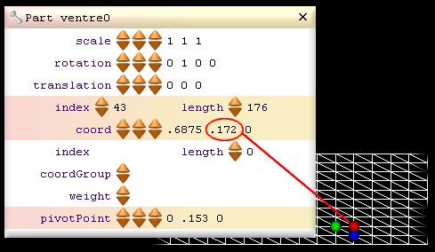
29. Set bands for thorax
This is much the same as for the tummy except the stem's height field for the first ring in the thorax is set to the same height that was specified for the tummy's last ring (.172).30. Set bands for pelvis
The top 4 segment are deleted and the endSP field is unchecked.31. Add blue parts for source
2 blue parts (ImmediatePart nodes) are added to the Seamless node so that the poly maps for the pelvis and thorax can be hand edited. Build nodes can not directly generate triangles for blue parts in a build cycle but unlike white parts which delete all their triangles at the beginning of each build cycle, blue parts retain their triangles from one build cycle to the next.References to the blue parts are added to the stems for the source triangles by dragging the blue parts to the blue dots (right of the stems) while holding down the Alt key. Adding a source reference to a stem causes the stem to use a copy of the poly map from the source part instead of generating a poly map. Because our source parts do not yet contain any triangles, the thorax and pelvis will be built containing no triangles.
32. Copy poly map from white to blue parts
Before copying the polymap from the thorax's stem to the thoraxMap part, the stem's
xJoinEnds field is unchecked because having triangles joining
back from east to west (the back facing side of the polymap) can
make hand editing a polymap confusing and because
we will be deleting the western half later anyway.Right click on the thorax's stem and select copy poly map to source to copy the stem's specified polymap to the source part.
For the pelvis the procedure is much the same except before copying the polymap to the pelvisMap part the stem node's southPole field is checked so that a south pole style poly map is used instead of the default mercator map. Same as for the world, flat polar maps distort the polar regions much less than flat mercater maps do. This only makes polar maps much easier to work with for the polar regions, the end results are exactly the same whether we use mercater or polar maps.
The following image shows the difference between a polar and mercator poly map for the pelvis:
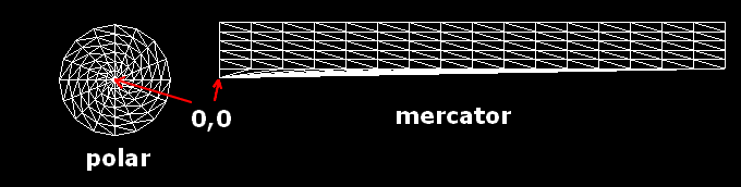
The coordinate at 0,0 is at the center of the south pole for both maps.
There is no need to uncheck the xJoinEnds field for a polar map because with polar maps all of the triangles will face us regardless of what xJoinEnds is set to.
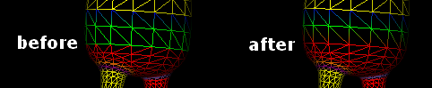
33. Delete hole for arm join
The FuseSurfaces's polyMapAid check box is checked to display a visual aid that shows where to make the hole in the poly map and where the arm's vertices will join. First delete the western half of the poly map (The deleted half will be mirrored back at a later stage) by clicking on a middle vertex and clicking . When we
select a vertex this way we should hold down the control key to prevent us from
accidently dragging the vertex. Because when ever we click on a vertex its x, y
and z components are
displayed in the control panel's coord field we can verify
we have the middle vertex be seeing if the x component equals .5
. When we
select a vertex this way we should hold down the control key to prevent us from
accidently dragging the vertex. Because when ever we click on a vertex its x, y
and z components are
displayed in the control panel's coord field we can verify
we have the middle vertex be seeing if the x component equals .5The closer we zoom in on a poly map the more accurate our editing will be. The Scene tree and control panel can be closed to give maximum editing space.
To center the view around the selected vertex click the
 button.
Because we don't want to drag any vertex in the z dimension when editing a poly map we should work with the
view. The z component is ignored from the poly map so dragging into the z dimension
wont cause problems for the end result but a non flat poly map may confuse us.When ever we click on a vertex not only will we select a vertex, a triangle will also be selected. The red, green and blue dots mark the selected triangle and the red and green dots mark the selected edge of the triangle. We can specify which triangle we wish to select by holding down the Alt key and clicking on any of the space within a triangle. We can specify which edge we wish to select when we select a triangle by clicking nearest to the desired edge.
Selected triangles are deleted by clicking
 .
.
To join a vertex to another, drag the vertex to the other and click
 .
.A triangle can be split down the selected edge by clicking
 .
.To create a new triangle from the last vertex that was copied
 and the selected edge
click
and the selected edge
click
 .
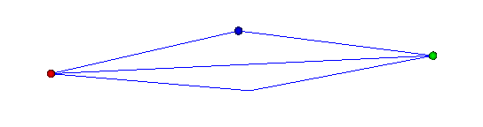
.Often we have two triangles divided like this:
when we would rather them be divided like this:
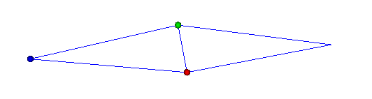
To swap the triangle divide first select the edge that divides the 2 triangles (it
does not matter which of the two triangles is selected so long as the dividing edge
is selected) and click
 .
.
The robot performs this operation quickly using only the tool bar and we can be even faster if we use the immediate editing short cut keys.
34. Nurbs Surface Poly Editing (NSPE)
In the previous operation the triangles were edited as a poly map (when the triangle are at the flat stage). In this operation we continue to edit the triangles but after they have been curved into shape by the NurbsPatch. This may appear to be plain poly modeling but we are in fact still editing the poly map but in an indirect way. What does this mean exactly? When we drag a vertex we are sliding it along the nurbes surface and can never drag it off the nurbs surface. Same goes for any of the other immediate commands when used for a white part (such as splitting a triangle or joinning a vertex), all of the vertices will lie exactly on the surface generated by the NurbsPatch. This is why we call this nurbs surface poly editing (NSPE). NSPE may seem much more straight forward and it certainly can make editing a poly map more intuitive but we must not forget we are in fact editing a flat 2d poly map for a NurbsPatch. If we understand this we will understand why it is illogical to join a vertex derived from one poly map to a vertex derived from another polymap.We should always have an ExitBuild node inserted immediately after our nurbs tree so that we ensure the order of all the vertices in the curved triangles corespond to the order of the vertices in the polymaps. If we don't pay attention to this we will likly experience behaviour that seems bizare when we use NSPE.
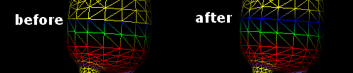
35. Delete hole for leg join
This is much the same as for the arm except we are working with a polar poly map and so when we delete the west half of the poly map we select a vertex who's x component equals 0 instead of .5Except for cutting the poly map in half, the robot uses NSPE for this operation because once we understand we are editing a poly map, there is no real need to edit the poly map directly.
If you are not convinced NSPE can save time, consider spliting a triangle. When you do this for poly modeling a new vertex is created exactly between 2 vertices so the new vertex has to be draged after for it to form part of the curved surface and this will have to be done using at least 2 different viewing orientations. This requires a lot of skill and even if we are very caperble polymodelers we will probably need to spend a good amount of time twirling our model to verify our vertices form a curved surface whereas when we split a triangle on a live nurbs surface we can rest assured the new vertex will lie exacly on the nurbs surface no matter what angle we are vieing it from and if we wish to drag any of the vertices that surround the new vertex (to optimise the poly structure) the same issues will apply.
Maintining active Nurbs Patches not only makes it easier to modify the poly structure while mainting the shape it also allows the artist to modify the shape at any time using only a few control points.
36. Fix torso, neck & head ownership
If now we click
and delete the ExitBuildinserted after the NurbsPatch tree, we will see our TransferOwnership
nodes no longer transfer all of the vertices as desired. We need to fix the
TransferOwnership nodes to accommodate the changes we made to the central parts. We no longer want to transfer any vertices from the pelvis. Like the pelvis
the thorax now gets vertices directly built for it so we wont have to transfer to
as many parts however we will now need an extra TransferOwnership because now 2 of the central
parts source triangles to other parts:tummt0 -> tummy1
neck0 -> neck1 & head
Because we are no longer transferring from a part whose rings begin with a single point we will no longer want any of the TransferOwnership beginSP fields checked.
37. Mirror pelvis & thorax
It is a good rule to insert the CopyPart node that copies the other halves back for the central parts immediately after all of the central parts have been transferred because this avoids a number of issues that can arise if inserted else where.38. Join vertical seams
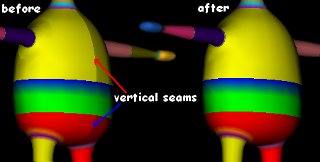
After all the geometry has been generated, mirrored and transferred in the build cycle, it is a good time to begin the phase of joining all the vertices.A JoinVertex node is straight forward to use. We simply plug in the parts we want to join, set the range field to how close we want the vertices to be to each other for them to join and check the in field if it is not already checked.
When joining vertices only within a part, only one part need be referenced if it is plugged in as the destination part. To plug in a part as the destination reference drag the part to the red dot (while holding down Alt):
Before clicking the in field orientate your view so that you can see the vertical seams easily. The seams should disappear soon as the in field is checked:
When we join vertices we are really replacing the source vertices with the destination vertices. This is why it is good to leave Seamless3d in coloured ownership mode while joining vertices. If however we want to see which colours (not to be confused with the ownership colors) are retained after joining vertices, we will need to turn coloured ownership mode off. Because more than one colour (or texture coordinates if textures are used) can be used for a single vertex, both the source and destination colours can be retained after the vertices are joined. This is achieved if both the srcColor and dstColor fields are left checked. If one of the 2 fields are un-checked only the source or destination colours are retained. Typically when using textures it is necessary to retain both the source and destination texture coordinates or the texture map will get messed up but when using color per vertex often only one colour is needed. The advantage in specifying only one colour is less vertices will have to be processed by your computer behind the scenes and files that are exported to a real time format are likely be smaller.
39. Join tummy to pelvis
To join one part's vertices to another part's vertices the source part must be dragged to the blue dot and the destination part must be dragged to the red:
40. Join thorax to tummy
41. Join thorax to neck

[3d Modelling Software] [Tutorials] [Forum] [Features] [Download] [Gallery] [FAQ] [Worlds] [Avatars] [Links] [Thyme]